Installing solar panels on a home is more than placing modules on a sunny roof. It requires careful planning, accurate measurements, and professional electrical work. A successful residential solar installation begins with a roof inspection. Check its age, structure, pitch, and areas affected by shade. Nearby trees, chimneys, and buildings can reduce daily energy production. Even a small shadow may affect several connected panels.
Homeowners should review electricity bills before choosing a system size. A qualified installer can compare annual energy use with local sunlight conditions. They should also explain panel efficiency, inverter options, battery storage, warranties, and expected maintenance. Ask for itemized costs. Ask about experience, certifications, insurance, and previous projects in similar homes. These details help separate reliable advice from attractive sales promises.
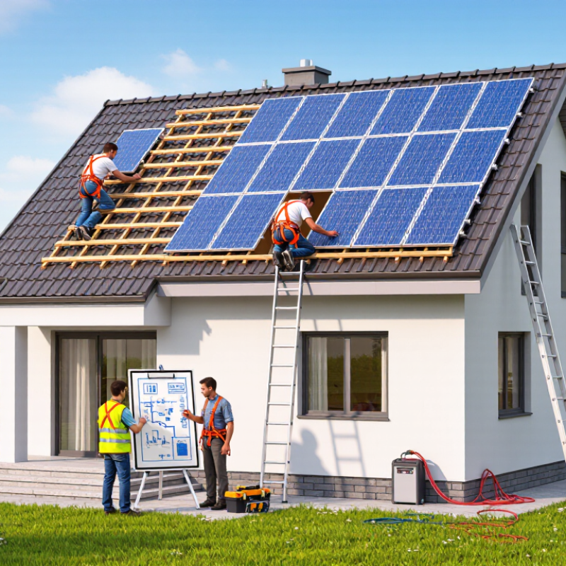
Permits, utility approvals, and local electrical requirements must be confirmed before installation. A licensed professional should design the wiring and complete grid connections safely. Never treat rooftop work as a weekend experiment. Falls, damaged shingles, and incorrect wiring can create serious risks. The process usually includes site assessment, system design, permitting, mounting, panel installation, inverter setup, inspection, and utility approval.
The work is rarely perfect on the first attempt. A roof sketch may reveal an unexpected vent. A cloudy week may complicate performance estimates. Good installers document these issues and adjust the plan openly. With realistic expectations and qualified guidance, solar power can become a dependable long-term investment rather than a rushed purchase.
How to Install Residential Solar Panels?
Assess Your Home and Solar Energy Needs
A reliable installation begins with your home, not a panel catalogue. Review twelve months of electricity bills and note seasonal peaks. The U.S. Energy Information Administration reported average household electricity use of 10,791 kilowatt-hours in 2023. Your usage may differ sharply.
Inspect the roof from the ground and attic. Look for cracked shingles, weak framing, moss, and afternoon shade. A south-facing roof often performs well in the Northern Hemisphere, but roof angle and local weather also matter. Trees can quietly reduce production. Use a site survey or NREL’s PVWatts tool to estimate annual output. Then compare that estimate with your actual consumption. Lawrence Berkeley National Laboratory’s 2024 Tracking the Sun report found a median residential system size of about 7.4 kilowatts in 2023. That figure is useful, but copying it blindly is a mistake. Your roof may need fewer panels or a larger system.
Tips: Check future electricity needs before sizing the system. An electric vehicle, heat pump, or home extension can increase demand. Examine your utility’s export rules and connection limits. Ask a qualified installer for a written shade analysis, structural assessment, and production forecast. I would also leave room for uncertainty. Weather varies, equipment ages, and estimates are never guarantees. A modest battery may help during outages, but it can raise costs considerably.
This chart compares typical monthly electricity use in a U.S. home with estimated output from a 6 kW residential solar system. Household consumption is based on an annual average of approximately 10,800 kWh, while solar production varies by season because of changing sunlight conditions. Compare your utility bills and local solar estimates before selecting a system size.
How to Install Residential Solar Panels?
Choosing a residential solar system starts with the home, not a product catalog. Inspect roof age, slope, shading, and available area. A sun-facing roof may perform well, but orientation is not the only concern. Trees, chimneys, and nearby buildings can create moving shadows. Record electricity use across seasons, including heating and cooling peaks. Then size the array, inverter, and battery around realistic demand. Oversizing can waste money. Undersizing may leave expected savings out of reach. A qualified designer should review structural loads and roof penetrations before installation. Ask for a clear layout, estimated annual production, equipment specifications, and maintenance access.
Permit requirements vary by municipality, utility, and property type. Contact the local building department before signing a final installation contract. You may need electrical, structural, zoning, or fire-safety approvals. Some areas also require an interconnection application for exporting electricity to the grid. Prepare a site plan, single-line electrical diagram, roof details, equipment data, and installer credentials. Check whether inspections are required at specific stages. Do not assume an online approval covers every review. It may not. Keep copies of applications, approval letters, inspection reports, and utility correspondence. These records can protect you if ownership or equipment changes later.
One common field mistake is showing the wrong roof section on a drawing. A small mismatch can create another inspection visit. That lesson is easy to overlook. Compare the approved design with the physical roof before work begins. Confirm conduit routes, emergency access paths, disconnect locations, and meter changes. If the design changes, ask whether revised permits are necessary. A careful installer should explain each step plainly, without pressure. Ask who submits permits, schedules inspections, and corrects failed work. Good paperwork is less exciting than panels, but it prevents expensive surprises.
How to Install Residential Solar Panels?
Prepare the roof before lifting any panels. Inspect shingles, tiles, flashing, and rafters for damage or movement. A weak roof should be repaired before installation begins. Check the roof’s age, slope, drainage, and expected snow or wind loads. A qualified installer should verify the structure and follow local building requirements. I once overlooked a small area of softened decking during planning. That mistake could have caused costly delays.
Mark the rafter positions from inside the attic when possible. Use accurate measurements, not visual estimates. Secure the mounting feet into solid structural members. Keep the rail layout square and evenly spaced. Seal every roof penetration with suitable flashing and weatherproof materials. Do not rely on surface sealant alone. After positioning the rails, check alignment with a level and tighten fasteners to the specified torque. Uneven rails can stress the panel frames.
Tips: Photograph the roof before work starts. Record rafter locations and fastener positions. Keep walking areas clear to reduce tile damage. Recheck every flashing point after rainfall. If anything feels uncertain, pause and consult a licensed roofing or electrical professional. My own plans have needed revision before; careful correction is better than confident rework.
| Installation Category | Inspection or Installation Item | Typical Residential Value or Requirement | Why It Matters |
|---|---|---|---|
| Roof condition | Roofing material and remaining service life | Confirm the roof is structurally sound; replace deteriorated roofing before installation. Asphalt-shingle roofs commonly last about 15–30 years, depending on material and climate. | Solar equipment can remain in service for decades, so installing it over a roof that needs replacement can increase future labor and removal costs. |
| Roof structure | Rafter or truss location | Locate and mark every framing member before drilling. Common residential rafter or truss spacing is approximately 400–600 mm (16–24 in) on center. | Mounting fasteners must transfer panel, rail, wind, and snow loads into the building structure rather than only into the roof covering. |
| Structural assessment | Additional dead load | A typical rooftop photovoltaic system, including modules and mounting hardware, often adds approximately 10–25 kg/m² (2–5 lb/ft²), but the actual value must come from the selected equipment. | The roof framing must support the added permanent weight as well as local wind, snow, and seismic forces. |
| Roof layout | Clearances and access paths | Maintain clearances required by local fire and building codes. Common design considerations include roof edges, ridges, valleys, hips, eaves, vents, skylights, and pathways for emergency access. | Correct setbacks reduce fire-service obstructions and prevent conflicts with drainage, roof penetrations, and maintenance areas. |
| Solar exposure | Shade and roof orientation | Evaluate shading from trees, chimneys, parapets, and nearby buildings throughout the year. In the Northern Hemisphere, south-facing roof planes generally receive strong annual solar exposure; east- and west-facing planes can also be suitable. | Shade and orientation affect annual energy production and help determine the most effective panel layout. |
| Mounting layout | Rail and attachment positions | Position rails according to the module manufacturer’s approved clamping zones. Rail spacing is commonly around 600–1,200 mm (24–48 in), but the final spacing depends on module size, rail capacity, wind, snow, and the mounting-system design. | Correct attachment spacing prevents excessive module or rail deflection and distributes loads properly. |
| Roof attachments | Flashing and waterproofing | Use a purpose-designed flashing or waterproof attachment assembly. Flashing should be installed beneath the upper roofing course and over the lower course so water sheds away from the penetration. | The flashing detail, not sealant alone, provides the primary long-term defense against roof leaks. |
| Fasteners | Lag screws or structural screws | Use corrosion-resistant fasteners sized for the approved attachment system. Fasteners must penetrate the specified structural member by the manufacturer’s required embedment; do not estimate embedment from roof thickness alone. | Insufficient embedment, incorrect diameter, or missed framing can significantly reduce pull-out and shear resistance. |
| Rail installation | Rail alignment and leveling | Install rails parallel to the planned module rows, keep attachment points aligned with framing, and tighten hardware to the mounting-system torque specification, commonly measured in N·m. | Straight, correctly torqued rails support consistent module clamping and reduce mechanical stress. |
| Module clamps | End and mid-clamp placement | Place clamps only within the module’s approved clamping range, maintain the specified module-to-module gap, and tighten each clamp to the equipment manufacturer’s torque value. | Incorrect clamp location or torque can damage the frame or reduce resistance to wind uplift. |
| Thermal movement | Rail expansion gaps | Provide expansion joints or rail gaps where required by the mounting-system instructions, especially on long rail runs. Follow the specified gap dimension for the selected system. | Allowing for thermal expansion helps prevent rail buckling, fastener stress, and module movement. |
| Grounding and bonding | Metallic components | Bond rails, module frames, and other exposed conductive parts as required by the applicable electrical code and the mounting-system instructions. Use listed grounding and bonding hardware. | A continuous grounding path helps reduce shock hazards and supports electrical fault protection. |
| Weather protection | Cable routing and penetrations | Route cables away from sharp edges and standing water, secure them with outdoor-rated clips, maintain bend-radius requirements, and seal any roof penetrations with approved methods. | Proper cable management limits abrasion, ultraviolet damage, water entry, and connector stress. |
| Environmental design | Wind, snow, and seismic loads | Use the site-specific design loads required by local code. Wind uplift and snow load calculations must consider roof height, exposure, roof slope, module arrangement, and edge zones. | A mounting layout suitable for one location may be inadequate in another because environmental loads vary substantially. |
| Final inspection | Fastener, flashing, and structural checks | Verify every attachment is connected to framing, flashing is correctly layered, rails are secure, clamps are correctly positioned, and all specified hardware is torqued and documented. | A documented final inspection helps identify installation defects before modules are commissioned and before severe weather occurs. |
Note: Dimensions and load values shown are typical planning ranges, not universal installation specifications. Final structural design, roof penetrations, setbacks, fastening, grounding, and permits must comply with the equipment instructions and applicable local building, fire, and electrical codes.
Panel attachment begins with the roof, not the panel. Inspect shingles, rafters, flashing, and water paths before drilling. Mark each rail carefully. A small alignment error can multiply across the array.
Use approved mounting hardware and tighten clamps to the manufacturer’s torque specification. Keep panels evenly spaced. Secure outdoor cables beneath the modules, away from sharp metal edges and standing water. Leave enough slack for thermal movement, but do not create hanging loops. The International Energy Agency’s Renewables 2024 report recorded nearly 420 gigawatts of new solar photovoltaic capacity worldwide in 2023. That scale makes consistent installation practices increasingly important.
Plan the electrical wiring before connecting anything. Confirm string voltage, polarity, current, and inverter limits. Route conductors through suitable conduit where required, then complete grounding, bonding, disconnects, and labels according to local electrical rules. Only qualified personnel should make service-panel connections. Lawrence Berkeley National Laboratory’s Tracking the Sun 2024 report found that the median U.S. residential system reached about 7.4 kilowatts in 2023. Larger arrays demand better cable planning.
Test continuity, polarity, insulation resistance, and open-circuit voltage before energizing the system. Check every connector. One loose connection can generate heat. The wiring diagram may look simple, but real roofs rarely are. I would photograph cable routes and record test results for future maintenance. A tidy installation is valuable, yet tidy does not always mean correct. Recheck it.
Inspecting a solar power system begins with the roof, not the wiring. Check the roof surface, flashing, structural supports, and signs of water damage. Measure shading during different times of day. A small chimney shadow can reduce production more than expected. Inspect each panel for cracked glass, loose frames, or damaged cables. Confirm that the mounting hardware matches the roof structure and local requirements. Do not improvise here.
Next, connect the system under the approved wiring plan. Keep cable connectors dry, firmly seated, and away from sharp metal edges. Route cables neatly beneath the panels, leaving enough slack for thermal movement. The inverter, disconnects, grounding conductors, and service panel need clear labels. A licensed electrician should verify every electrical connection. One loose terminal can create heat, faults, or equipment damage.
Activation should be deliberate. Confirm that permits, utility approval, and required inspections are complete. Turn on disconnects in the sequence stated by the equipment instructions. Watch the inverter display for fault codes, abnormal voltage, or missing communication. Test monitoring data against the meter when possible. Record the activation date, readings, and inspection notes. The process may not look perfectly tidy after the first visit. That is a reason to review it again, not ignore small concerns. If anything seems uncertain, stop and request qualified assistance.